A cooling or heating water distribution system is in balance when the flow in the whole system (through the component terminal lines, distributing lines and main distributing lines) corresponds to the flow rates that were specified for the design of the system. If the correct balancing of the system is not established, this will result in unequal distribution of the flow, so that there will be a surplus effect in some of the terminals, whereas the effect will be inadequate in others. As a consequence, the required heating or cooling will not be ensured in all parts of the installation. Practically, it is not possible to achieve a completely balanced system by manipulation of the piping or alteration of the pipe dimensions only. Only a correct set of balancing valves can ensure the correct distribution of the flow in the system.
Balancing valves are used in hydronic systems to adjust and proportion the flow through various branches and mains to various portions of the system. If balancing valves are omitted from the piping system, the flow will take the path of least resistance, which may result in some sections of the system not receiving any flow. As an example, the use of a balancing valve on a warm-water heating coil will limit the flow through that coil, limiting the amount of energy used to heat the air passing across the coil.
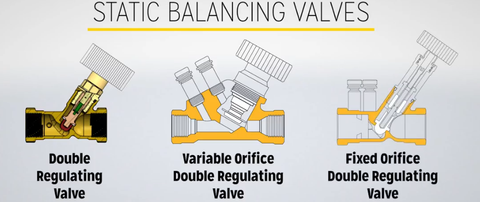
Balancing Valve Types The three most common balancing valve configurations are (1) calibrated manual balancing valve, (2) flow-measuring venturi or orifice plate with manual ball or butterfly valve, and (3) automatic flow-limiting (or automatic flow control) valve.
Calibrated Manual Balancing Valve Types Calibrated manual balancing valves consist of a valve and pressure ports on each side of the valve. They are calibrated by the manufacturer and should have a chart and/or a Cv coefficient that are specific to that valve. Calibrated manual balancing valves can be one of the following types: globe, plug, butterfly, or eccentric valves. Gate valves are for on/off service only, and should not be used for balancing. A brief description of each type of calibrated manual balancing valve follows.
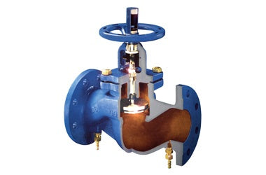
Globe Type The globe-type calibrated manual balancing valve has a closing mechanism in the form of a disc or a plug which moves on an axis perpendicular to the seat. The globe-calibrated manual balancing valve can be manufactured in a variety of ways to meet the requirements of the system. The globe-type calibrated manual balancing valve is the best choice for proper balancing of a system, and it has the greatest pressure drop of any of the calibrated manual balancing valves available.
Plug Type The plug-type calibrated manual balancing valve has a conical-shaped closing mechanism that is wedged into the body of the valve to create a proper seal. This plug valve should only be used on smaller-size pipes. Plug valves should not be throttled to almost closed. Throttling a plug valve to almost closed could damage the valve.
Butterfly Type The butterfly-type calibrated manual balancing valve has a rotating disc for the closing mechanism. The disc is always in the flow. This butterfly valve, on occasion, has been used for balancing. The problem with using the butterfly valve for balancing is that when throttling, the disc may begin to vibrate, creating undue stress on the valve.
Eccentric Type The eccentric-type, calibrated-manual balancing valve is similar to the butterfly valve except for one difference. The disc in the valve is made for throttling. Fluid is allowed to pass on only one side of the valve, thus eliminating any vibration problems associated with using a butterfly valve.
Flow-Measuring Venturi or Orifice Plate A flow-measuring venturi or an orifice plate with a manual ball or butterfly valve is a simple combination of two separate components. The valve is located at least 10 pipe diameters upstream of the flow measuring device. By closing the valve, the flow becomes restricted. A pressure drop reading is obtained from the venturi or orifice plate. Comparing the pressure drop to the instrument's calibration chart will provide the flow rate.
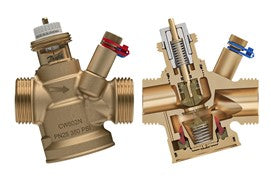
Automatic Flow-Limiting Valves Automatic flow-limiting (or automatic flow control) valves have a controller on the valve stem. The controller modulates the valve from open to closed or to any point in between. The controller is connected to an activating device such as a thermostat. If the thermostat calls for more heat from the coil, the controller will drive the stem open. If the thermostat calls for less heat, the controller will drive the stem closed.
Balancing Valve Installation Balancing valves should be located after the control valve on the return sides of all terminal units. The supply side of all terminal units should use a gate valve or ball valve for shut-off. This balancing-valve location will insure a positive pressure on the coil to permit positive air removal through the automatic air vent. This valve configuration will also allow the balancing valve and the supply valve to be closed to permit servicing of the terminal coil or the control valve. In some cases, a balancing valve or a multipurpose valve located on the pump discharge can be used to measure total flow to determine if the pump impeller should be trimmed. Once the pump is trimmed or replaced, this valve should be opened fully.
Balancing valves shall be installed to correspond with the correct flow direction. There is usually an arrow located on the valve to indicate the correct flow direction for installation. The valve should be in the upright position with the pressure ports fully accessible for hook-up with the measuring hoses. A 90° rotation to the side is allowed in most cases, but should be avoided when possible.
Write us your Comments or Suggestions :-
Use left/right arrows to navigate the slideshow or swipe left/right if using a mobile device
choosing a selection results in a full page refresh
press the space key then arrow keys to make a selection